해당 포스트은 뮌헨 공과대학교(TU München)의 Prof. Dr. Daniel Cremers 께서 진행하신 Multiple View Geometry 강의를 정리한 내용입니다.
Multiple View Geometry 과목의 세번째 강의는 투영 기하학과 관련된 내용이 포함되어 있습니다.
Mathematics of Perspective Projection
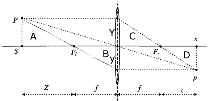
위의 그림은 point P가 image p에 투영되는 상황을 보여주고 있습니다.
이때 P는 좌표 $\textbf{X} = (X, Y, Z) \in R^3$를 가지고 있으며, 이는 z축이 lens의 optical axis이고 optical center에 대한 reference frame에 대한 좌표입니다.
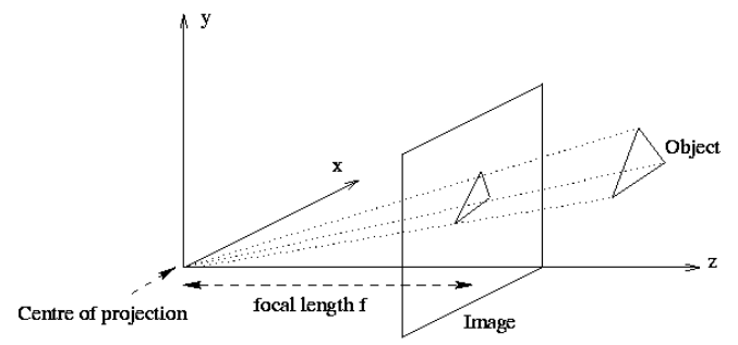
위의 그림에 따르면, 실제로 맺히는 상 image p는 랜즈 뒤에 생기게 되지만 이를 대칭이동하여 랜즈 앞(point P와 같은 방향)으로 옮겨 아래 그림과 같이 생각한다면 앞으로의 계산이 한결 쉬워집니다.
이를 이용하여 perspective transformation $\pi$를 다음과 같이 나타낼 수 있으며, 이는 위의 그림에서 point와 image 사이에 매칭되는 점에 대한 비례를 통해 유도될 수 있습니다.
\[\pi : R^3 \rightarrow R^2 \;\;\;\;\;\; \textbf{X} \rightarrow x = \pi (\textbf{X}) = \begin{pmatrix} f \frac{X}{Z}\\ f \frac{Y}{Z} \end{pmatrix}\]An Ideal Perspective Camera
위의 perspective transformation은 homogeneous coordinate에서 다음과 같이 표현될 수 있습니다.
\[Z \textbf{x} = Z \begin{pmatrix} x \\ y \\ 1 \end{pmatrix} = \begin{pmatrix} f & 0 & 0 & 0 \\ 0 & f & 0 & 0 \\ 0 & 0 & 1 & 0 \end{pmatrix} \begin{pmatrix} X \\ Y \\ Z \\ 1 \end{pmatrix} = K_f \Pi_0 \textbf{X}\]이때, $\textbf{x}$는 image의 좌표, $\textbf{X}$는 point의 좌표이며 $K_f, \Pi_0$는 다음과 같습니다.
\[K_f \equiv \begin{pmatrix} f & 0 & 0 \\ 0 & f & 0 \\ 0 & 0 & 1 \end{pmatrix} \;\;\;\;\;\; \Pi_0 \equiv \begin{pmatrix} 1 & 0 & 0 & 0 \\ 0 & 1 & 0 & 0 \\ 0 & 0 & 1 & 0 \end{pmatrix}\]여기서 matrix $\Pi_0$는 standard projection matrix라고 하며, $Z$가 0 이상의 상수, $\lambda$라고 하면 다음과 같습니다.
\[\lambda \textbf{x} = K_f \Pi_0 \textbf{X}\]이전에 나왔던 camera의 rigid motion을 통해 다음과 같이 world 좌표계의 point $\textbf{X}_0$에서 camera 좌표계의 point $\textbf{X}$를 얻을 수 있습니다.
\[\textbf{X} = R \textbf{X}_0 + T\]Homogeneous 좌표계 $\textbf{X} = (X, Y, Z, 1)^T$ 로 표현하는 경우에는 다음과 같습니다.
\[\textbf{X} = g \textbf{X}_0 = \begin{pmatrix} R & T \\ 0 & 1 \end{pmatrix} \textbf{X}_0\]이들을 결합하면, 다음과 같이 world 좌표계에서 image 좌표계로의 transformation을 얻을 수 있습니다.
\[\lambda \textbf{x} = K_f \Pi_0 g \textbf{X}_0\]또한 focal length $f$ 가 알려져 있어 이를 1로 normalize(image 좌표계의 unit을 바꿈으로써 normalize 할 수 있음) 할 수 있는 경우 다음과 같이 표현됩니다.
\[\lambda \textbf{x} = \Pi_0 \textbf{X} = K_f \Pi_0 g \textbf{X}_0\]Intrinsic Camera Parameters
만약 카메라의 중심이 optical center와 일치하지 않거나, pixel 좌표가 unit scale이 아니거나, 또는 pixel이 정사각형이 아닐 경우 이를 처리하기 위한 transformation parameter가 더 필요합니다.
이를 고려하여 pixel 좌표 $(x’, y’, 1)$을 homogeneous camera coordinate $\textbf{X}$의 함수로 나타내면 다음과 같습니다.
\(\lambda \begin{pmatrix} x' \\ y' \\ 1 \end{pmatrix} = \begin{pmatrix} s_x & s_{\theta} & o_x \\ 0 & s_y & o_y \\ 0 & 0 & 1 \end{pmatrix} \begin{pmatrix} f & 0 & 0 \\ 0 & f & 0 \\ 0 & 0 & 1 \end{pmatrix} \begin{pmatrix} 1 & 0 & 0 & 0 \\ 0 & 1 & 0 & 0 \\ 0 & 0 & 1 & 0 \end{pmatrix} \begin{pmatrix} X \\ Y \\ Z \\ 1 \end{pmatrix}\) = K_s K_f \Pi_0 \textbf{X}
이때, $K_s$가 위에서 설명한 추가적인 transformation이며, perspective projection $\Pi_0$ 이후에 적용되는 transformation인 $K = K_s K_f$를 intrinsic parameter matrix라고 하며, 다음과 같이 정리할 수 있습니다.
\[K \equiv K_s K_f = \begin{pmatrix} fs_x & fs_{\theta} & o_x \\ 0 & fs_y & o_y \\ 0 & 0 & 1 \end{pmatrix}\]위에 표기된 각 기호의 의미는 다음과 같습니다.
- $o_x$ : x-coordinate of principal point in pixels (카메라의 중심이 optical center와 일치하지 않을 때 필요한 parameter)
- $o_x$ : y-coordinate of principal point in pixels (카메라의 중심이 optical center와 일치하지 않을 때 필요한 parameter)
- $fs_x = \alpha_x$ : size of unit length in horizontal pixels (pixel 좌표가 unit scale이 아닐 때 필요한 parameter)
- $fs_y = \alpha_y$ : size of unit length in vertical pixels (pixel 좌표가 unit scale이 아닐 때 필요한 parameter)
- $\alpha_x / \alpha_y$ : aspect ratio $\sigma$
- $fs_{\theta}$ : skew of the pixel, often close to zero (pixel이 정사각형이 아닐 경우 필요한 parameter)
그리고 위의 식을 world coordinate $\textbf{X}_0$로 나타내면 다음과 같습니다.
\[\lambda \textbf{x}' = K \Pi_0 \textbf{X} = K \Pi_0 g \textbf{X}_0 \equiv \Pi \textbf{X}_0\]여기서 $3 \times 4$ matrix $\Pi \equiv K \Pi_0 g = (KR, KT)$를 genreal projection matrix라고 합니다.
그리고 아직 남아있는 scale parameter $\lambda$ 를 나누어 다음의 식을 얻을 수 있습니다.
\[x' = \frac{\pi^T_1 \textbf{X}_0}{\pi^T_3 \textbf{X}_0} \;\;\;\;\;\; y' = \frac{\pi^T_2 \textbf{X}_0}{\pi^T_3 \textbf{X}_0}\]여기서 $\pi^T_1, \;\; \pi^T_2, \;\; \pi^T_3 \in R^4$는 projection matrix $\Pi$의 3가지 row입니다.
Radial Distortion
Intrinsic parameter는 pixel coordinate로의 transformation에서 linear distortion을 나타낸다고 볼 수 있습니다.
그러나 저사양의 카메라 또는 넓은 field of view를 가지고 있는 카메라의 경우 radial axis 방향에 대한 distortion이 발생할 수 있습니다.
이러한 radial distortion을 모델링하는 간단한 식 중 하나는 다음과 같습니다.
\[x = x_d (1 + a_1r^2 + a_2r^4) \;\;\;\;\;\; y = y_d (1 + a_1r^2 + a_2r^4)\]여기서 $\textbf{x}_d = (x_d, y_d)$는 distorted point이며, $r^2 = x^2_d + y^2_d$입니다.
만약 calibration이 가능하다면 distortion parameter $a_1,a_2$를 알아낼 수 있습니다.
Radial distortion에 대한 더욱 일반적인 모델은 다음과 같습니다.(Devernay and Faugeras 1995)
\[\textbf{x} = c + f(r)(\textbf{x}_d-c) \;\;\;\;\;\; f(r) = 1 + a_1 r + a_2 r^2 + a_3 r^3 + a_4 r^4\]여기서 $r = \mid \textbf{x}_d -c \mid$는 distortion c 의 임의의 중심이며, distortion correction factor $f(r)$은 임의의 4-th order
Preimage of Points and Lines
Perspective transformation은 임의의 geometric entity에 대해 image를 정의할 수 있는 방법을 제시하고 있습니다.
하지만 알 수 없는 scale factor로 인해 각 point는 단일 지점 $\textbf{x}$에 mapping 되는 것이 아니라 equivalence class of points $\textbf{y} \sim \textbf{x}$에 mapping 됩니다.
이러한 현상은 직선이 어떻게 변환되는 지를 살펴봄으로써 관찰할 수 있습니다.
3D 상에서의 직선 L은 base point $\textbf{X}_0 = (X_0, Y_0, Z_0, 1)^T$와 vector $\textbf{V} = (V_1, V_2, V_3, 0)$을 이용하여 다음과 같이 나타낼 수 있습니다.
\[\textbf{X} = \textbf{X}_0 + \mu \textbf{V} \;\;\; \mu \in R\]이 line L의 image는 다음과 같이 주어집니다.
\[\textbf{x} \sim \Pi_0 \textbf{X} = \Pi_0(\textbf{X}_0 + \mu \textbf{V}) = \Pi_0 \textbf{X}_0 + \mu \Pi_0 \textbf{V}\]이때 나타나는 equivalent는 두 coordinate vector $\textbf{X}, \textbf{Y}$가 서로 scalar factor 차이만 날 때 서로를 equivalent
Origin o로 부터 vector로 표현되는 모든 $\textbf{x}$는 2D subspace P를 span하며, 이 plane P을 직선의 preimage라고 하며, preimage와 image plane이 교차되는 부분이 바로 주어진 line의 image입니다.
곡선이나 복잡한 모양에 대해서도 preimage는 정의되지만, 점 또는 직선에 대한 preimage는 $R^3$의 subspace입니다.
이러한 subspace는 orthogonal complement를 통해 표현될 수 있으며, preimage가 plane일 경우에는 normal vector로 나타납니다.
이렇게 나타나는 complement를 coimage라고하며, 점 또는 직선의 coimage는 $R^3$의 subspace이고, 그것의 preimage의 유일한 orthgonal complement입니다.
그리고 image, preimage, coimage는 다음과 같이 서로를 unique하게 결정하여 서로 equivalent합니다.
- image = $preimage \cap image plane$
- preimage = $span(image)$
- preimage = $coimage^{\perp}$
- coimage = $preimage^{\perp}$
Preimage의 모든 points, 즉 image의 모든 points $\textbf{x}$는 coimage를 span하는 normal vector $l \in R^3$에 수직입니다.
\[l^T \textbf{x} = 0\]그리고 $l$에 수직인 모든 vector들의 space는 $\hat{l}$의 row vector들에 의해 span됩니다.
\[P = span(\hat{l})\]Point p의 image $\textbf{x}$의 경우 preimge가 line이고, coimage는 $\textbf{x}$에 수직인 plane이며, 이는 matrix $\hat{x}$에 의해 span됩니다.
| Image | Preimage | Coimage | |
|---|---|---|---|
| Point | $span(\textbf{x}) \cap im.plane$ | $span(\textbf{x}) \subset R^3$ | $span(\hat{\textbf{x}}) \subset R^3$ |
| Line | $span(\hat{l}) \cap im.plane$ | $span(\hat{l}) \subset R^3$ | $span(l) \subset R^3$ |